Series 477
Dura-Hoist Helical/Worm Gear
Up to 907 kg Capacity
Anchor your operation with the reliability of Dura-Hoist. With solid construction, internal lubrication and pendant control, the only thing you won’t need is worry..
QUICK FACTS
- Machine cut gears
- Enclosed oil bath
- Internal mechanical brake
- Cast aluminum
- Ball bearings
- Large diameter drums
- Mounting options
- 2-Year Limited Warranty
SERIES MODELS
- 4771
Features
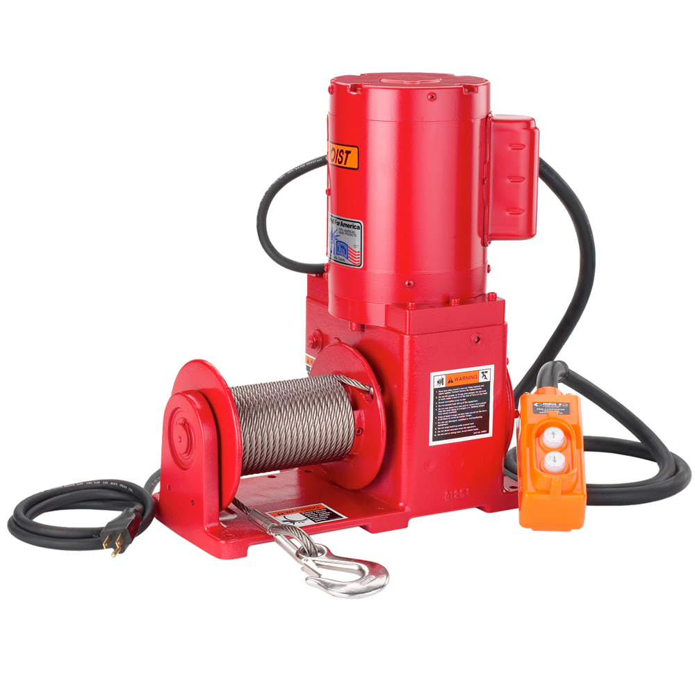
115/1/60 Electric Motor
Standard 115-volt single-phase motor includes power cord with grounded plug and a momentary contact-type push button pendant control on a control cord.
Cast Aluminium Construction
Rugged work site durability in a lightweight package.
Machine Cut Worm Gears
Bronze gearing provides accurate, high efficiency operation and long lasting service.
Enclosed Oil Bath
Gears operate with continuous lubrication to minimize wear. Oil seals keep oil in and dirt out.
Automatic Brake
Internal mechanical brake provides positive load control for lifting and lowering operations.
Bronze Ball Bearings
Bearings are self-aligning and provide smooth and efficient operation.
Large Diameter Drums
Minimize wear to extend wire rope life.
Narrow Drums
Designed with a 4 inch drum for tight fleet angle installations.
Corrosion Resistant
Durable paint finish combined with trivalent zinc plating protects against corrosion in harsh environments.
Two-Year Warranty
Industry-leading two-year limited warranty on all our products.
Performance Specs.
| Model No. | Motor Description | Motor HP | Load Rating | Line Speed | Drum Capacity ¹ | |||||||||||||||||
| 1st Layer | Mid Drum | Full Drum | Wire Rope Dia. | 1st Layer | Full Drum | 1st Layer | Mid Drum | Full Drum | Approx. Ship Weight | |||||||||||||
| (lb) | (kg) | (lb) | (kg) | (lb) | (kg) | (in) | (mm) | (fpm) | (mpm) | (fpm) | (mpm) | (ft) | (m) | (ft) | (m) | (ft) | (m) | (lb) | (kg) | |||
| 4771 ² | 115/1/60 VAC – 6 ft pendant | 1.2 | 2000 | 907.1 | 1500 | 680.3 | 1200 | 544.3 | 5/16 | 7.9 | 13 | 3.9 | 22 | 6.7 | 13 | 3.9 | 40 | 12.1 | 90 | 27.4 | 88 | 26.8 |
| 4771AC-1PH | 115/1/60 VAC – less controls | 1.2 | 2000 | 907.1 | 1500 | 680.3 | 1200 | 544.3 | 5/16 | 7.9 | 13 | 3.9 | 22 | 6.7 | 13 | 3.9 | 40 | 12.1 | 90 | 27.4 | 87 | 39.4 |
| 4771AC-1PH2 ³ | 115/230/1/60 VAC – less controls | 1.5 | 2000 | 907.1 | 1500 | 680.3 | 1200 | 544.3 | 5/16 | 7.9 | 13 | 3.9 | 22 | 6.7 | 13 | 3.9 | 40 | 12.1 | 90 | 27.4 | 115 | 42.1 |
| 4771AC-3PH ³ | 230/460/3/60 VAC – less controls | 1.5 | 2000 | 907.1 | 1500 | 680.3 | 1200 | 544.3 | 5/16 | 7.9 | 13 | 3.9 | 22 | 6.7 | 13 | 3.9 | 40 | 12.1 | 90 | 27.4 | 111 | 50.3 |
| 4771DC 4 | 12 VDC – 10 ft pendant | 1.0 | 2000 | 907.1 | 1500 | 680.3 | 1200 | 544.3 | 5/16 | 7.9 | 13 | 3.9 | 22 | 6.7 | 13 | 3.9 | 40 | 12.1 | 90 | 27.4 | 105 | 47.6 |
| 4771PN 4,5 | pneumatic – less controls | 1.2 | 2000 | 907.1 | 1500 | 680.3 | 1200 | 544.3 | 5/16 | 7.9 | 13 | 3.9 | 22 | 6.7 | 13 | 3.9 | 40 | 12.1 | 90 | 27.4 | 70 | 31.7 |
| 4771HY 4,5 | hydraulic – less controls | 2.3 | 2000 | 907.1 | 1500 | 680.3 | 1200 | 544.3 | 5/16 | 7.9 | 13 | 3.9 | 22 | 6.7 | 13 | 3.9 | 40 | 12.1 | 90 | 27.4 | 72 | 32.6 |
| 4777 ² | 115/1/60 VAC – 6 ft pendant | 1.2 | 2000 | 907.1 | 1500 | 680.3 | 1200 | 544.3 | 5/16 | 7.9 | 13 | 3.9 | 22 | 6.7 | 7 | 2.1 | 27 | 8.2 | 60 | 18.2 | 93 | 42.1 |
| 4777DC 4, 6 | 12 VDC – 10 ft pendant | 1.0 | 2000 | 907.1 | 1500 | 680.3 | 1200 | 544.3 | 5/16 | 7.9 | 13 | 3.9 | 22 | 6.7 | 7 | 2.1 | 27 | 8.2 | 60 | 18.2 | 105 | 47.6 |
| Please contact BTS for firm fixed price and delivery. ¹ Actual drum capacities may be 25-30% less due to non-uniform winding. Wire rope tension will also affect drum capacity. ² Motor includes an 8-foot power cord with grounded plug and a push button pendant control on 6-foot cord. ³ For models 4771AC-1PH2 and 4771AC-3PH, please specify voltage when ordering. 4 For pneumatic, hydraulic, and DC models, line speed is based on rated load, actual line speed varies with load weight and power supply. 5 For model 4771PN, ratings are for 80 cfm at 100 psi. For model 4771HY, ratings are for 4 gpm at 1000 psi. | ||||||||||||||||||||||
IMPORTANT: It is the owner’s or operator’s responsibility to determine the suitability of the equipment to its intended use. Study all applicable codes, manuals and regulations. Be sure to read the Owner’s Manual supplied with the equipment before operating it.
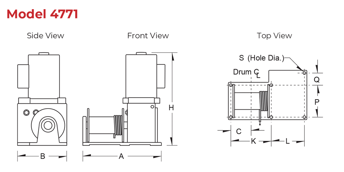
Winch Dimensions
Install wire rope correctly as shown, or brake will not operate properly
Dimensions
| 477 Series – Winch Dimensions | ||||||||||||||||||
| Model No | A | B | C | H | K | L | P | Q | S (hold dia.) | |||||||||
| (in) | (mm) | (in) | (mm) | (in) | (mm) | (in) | (mm) | (in) | (mm) | (in) | (mm) | (in) | (mm) | (in) | (mm) | (in) | (mm) | |
| 4771 | 14.38 | 365.2 | 8.86 | 225.0 | 3.55 | 90.1 | 17.45 | 443.2 | 6.75 | 171.4 | 6.31 | 160.2 | 5.70 | 144.7 | 2.16 | 54.8 | 0.34 | 8.6 |
| 4771AC-1PH | 14.38 | 365.2 | 8.86 | 225.0 | 3.55 | 90.1 | 22.00 | 558.8 | 6.75 | 171.4 | 6.31 | 160.2 | 5.70 | 144.7 | 2.16 | 54.8 | 0.34 | 8.6 |
| 4771AC-1PH2 | 14.38 | 365.2 | 8.86 | 225.0 | 3.55 | 90.1 | 21.00 | 533.4 | 6.75 | 171.4 | 6.31 | 160.2 | 5.70 | 144.7 | 2.16 | 54.8 | 0.34 | 8.6 |
| 4771AC-3PH | 14.38 | 365.2 | 8.86 | 225.0 | 3.55 | 90.1 | 19.00 | 482.6 | 6.75 | 171.4 | 6.31 | 160.2 | 5.70 | 144.7 | 2.16 | 54.8 | 0.34 | 8.6 |
| 4771DC | 14.38 | 365.2 | 8.86 | 225.0 | 3.55 | 90.1 | 18.69 | 474.7 | 6.75 | 171.4 | 6.31 | 160.2 | 5.70 | 144.7 | 2.16 | 54.8 | 0.34 | 8.6 |
| 4771PN | 14.38 | 365.2 | 8.86 | 225.0 | 3.55 | 90.1 | 14.94 | 379.4 | 6.75 | 171.4 | 6.31 | 160.2 | 5.70 | 144.7 | 2.16 | 54.8 | 0.34 | 8.6 |
| 4771HY | 14.38 | 365.2 | 8.86 | 225.0 | 3.55 | 90.1 | 11.84 | 300.7 | 6.75 | 171.4 | 6.31 | 160.2 | 5.70 | 144.7 | 2.16 | 54.8 | 0.34 | 8.6 |
| 4777 | 14.38 | 365.2 | 8.86 | 225.0 | 3.49 | 88.6 | 17.45 | 443.2 | 6.75 | 171.4 | 6.31 | 160.2 | 5.70 | 144.7 | 2.16 | 54.8 | 0.34 | 8.6 |
| 4777DC | 14.38 | 365.2 | 8.86 | 225.0 | 3.49 | 88.6 | 18.69 | 474.7 | 6.75 | 171.4 | 6.31 | 160.2 | 5.70 | 144.7 | 2.16 | 54.8 | 0.34 | 8.6 |
| Dimensions are for reference only and subject to change without notice. | ||||||||||||||||||
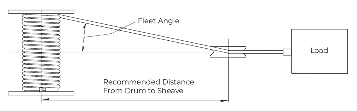
Drum Dimensions
| 4WP2D Series – Drum Dimensions | ||||||||
| Model Extension | Drum Dia. | Flange Dia. | Drum Width | Fleet Angle Distance ¹ | ||||
| (in) | (mm) | (in) | (mm) | (in) | (mm) | (ft) | (m) | |
| 4771 | 3.00 | 76.2 | 6.00 | 152.4 | 6.00 | 152.4 | 10 | 3.0 |
| 4771AC-1PH | 3.00 | 76.2 | 6.00 | 152.4 | 6.00 | 152.4 | 10 | 3.0 |
| 4771AC-1PH2 | 3.00 | 76.2 | 6.00 | 152.4 | 6.00 | 152.4 | 10 | 3.0 |
| 4771AC-3PH | 3.00 | 76.2 | 6.00 | 152.4 | 6.00 | 152.4 | 10 | 3.0 |
| 4771DC | 3.00 | 76.2 | 6.00 | 152.4 | 6.00 | 152.4 | 10 | 3.0 |
| 4771PN | 3.00 | 76.2 | 6.00 | 152.4 | 6.00 | 152.4 | 10 | 3.0 |
| 4771HY | 3.00 | 76.2 | 6.00 | 152.4 | 6.00 | 152.4 | 10 | 3.0 |
| 4777 | 3.00 | 76.2 | 6.00 | 152.4 | 4.00 | 101.6 | 7 | 2.1 |
| 4777DC | 3.00 | 76.2 | 6.00 | 152.4 | 4.00 | 101.6 | 7 | 2.1 |
| ¹ Recommended minimum distance between drum and lead sheave for smooth drum. Dimensions are for reference only and subject to change without notice. | ||||||||
Control Options and Accessories
| 4WP2D Series Control Options and Accessories | |||
| Model No. | Description | Approx. Ship Weight | |
| (lb) | (kg) | ||
| 10L2A1 ¹ | NEMA 1 control switch — mounted and wired | 3 | 1.4 |
| 10L2A41 ¹ | NEMA 4 watertight control switch — mounted and wired | 7 | 3.2 |
| 477PN-CNTRL | Pneumatic control valve (not mounted or plumbed, no hoses) | 6 | 2.7 |
| 477PN-HS6 | 6-ft hoses for pneumatic controls (not plumbed) | 4 | 1.8 |
| 477HY-CNTRL | Hydraulic control valve (not mounted or plumbed, no hoses) | 5 | 2.3 |
| 477HY-HS6 | 6-ft hoses for pneumatic controls (not plumbed) | 4 | 1.8 |
| ¹ Controls for 115V, single phase, 60 cycle include an 8-ft power cord with grounded plug. Please contact factory or nearest Thern Distributor for firm fixed price and delivery. | |||
Accessories / Options
Vertical Lead Block
The Redline Series is used to change the direction of the rope, so the winch can be mounted in a convenient location and the Redline Lead Block will control the path of the rope to avoid obstacles, reduce hazard, and improve rope wear. Vertical Lead Block Series
Mounting Options
Floor, wall, or ceiling mount configurations available.
Emergency Hand Crank
Allows for manual operation in case of power failure. Does not include handle.
Rotary Limit Switches
Provides secondary shut-off to limit load travel in one or two directions. Not available on clutch models.
Pressure Plate
Applies pressure to drum and wire rope to help maintain uniform winding.
Special Motors and Controls
Available in a wide range of standard and custom configurations for single or variable speed, including severe duty and explosion proof. Motors also available in hydraulic and pneumatic.
Special Finishes
Available for operation in harsh or hazardous environments.
Torque Limiters
Available as part of the motor controls on electric models.