DOUBLE REDUCTION SERIES WINCHES
Up to 4,535kg Capacity
When you need to lift, lower or position a heavy load, Thern’s spur gear hand winches are designed to deliver excellent performance and long life, no matter what your application.
QUICK FACTS
- Up to 10,000 lb (4,535kg) capacity
- Machine-cut spur gears
- Variety of configurations
- Adjustable handles
- Corrosion resistant
- Two-Year Limited Warranty
SERIES MODELS
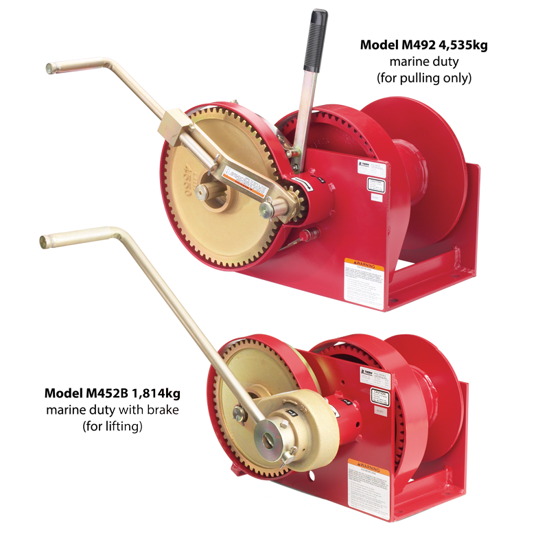
- M452/M452B
- M452B-A
- M492/M492B
- M492-12/M492B-12
Features
Machine Cut Spur Gears
For accurate and long lasting service.
Automatic Brake Models
Provide positive load control for lifting and lowering operations. Brake models have B suffix.
Corrosion Resistant
Trivalent zinc plated finish protects against corrosion in harsh environments.
Bronze and Radial Ball Bearings
Provide smooth and efficient operation.
Large Diameter Drums
Minimize wear to extend wire rope life.
Spring Loaded Ratchets
For positive engagement with gear.
Steel Gear Covers
Protect gears and help prevent injuries.
Adjustable Handles
Handles adjust in length to change force required to move load.
Two-Year Warranty
Industry-leading two-year limited warranty on all our products
Accessories / Options
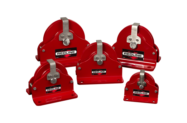
Vertical Lead Block
The Redline Series is used to change the direction of the rope, so the winch can be mounted in a convenient location and the Redline Lead Block will control the path of the rope to avoid obstacles, reduce hazard, and improve rope wear.
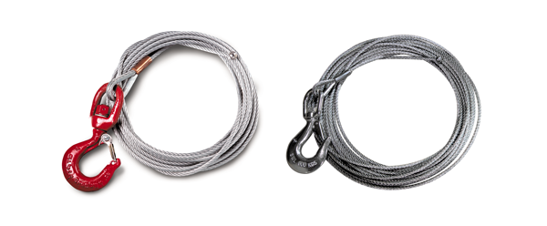
Wire Rope Assemblies
rope-assemblies-500Galvanized or stainless steel wire rope assemblies, available in various lengths.
Performance Specs.
| Spur Gear Double Reduction Hand Winches Performance Characteristics — Metric | ||||||||||||
| Load Rating | Drum Capacity1 | |||||||||||
| Model No. | Description | 1st Layer | Mid Drum | Full Drum | Wire Rope Dia.1 | 1st Layer | Mid Drum | Full Drum | Sgl Gear Ratio | Dbl Gear Ratio | Force3 to Lift 453.5 kg | Approx. Ship Wt. |
| (kg) | (kg) | (kg) | (mm) | (m) | (m) | (m) | (kg) | (kg) | ||||
| M452 | 4000 lb — marine duty | 1814 | 1496 | 1133 | 6.3 | 7.0 | 39.6 | 91.4 | 4.42:1 | 19.54:1 | 4.5 | 38 |
| (for pulling only) | 7.9 | 5.4 | 27.1 | 60.9 | (dbl gear) | |||||||
| 9.5 | 4.2 | 19.5 | 42.6 | |||||||||
| M452B | 4000 lb — marine duty | 1814 | 1496 | 1133 | 6.3 | 7.0 | 39.6 | 91.4 | — | 19.54:1 | 4.5 | 42 |
| with brake (for lifting only) | 7.9 | 5.4 | 27.1 | 60.9 | (dbl gear) | |||||||
| 9.5 | 4.2 | 19.5 | 42.6 | |||||||||
| M452B-A | 4000 lb — marine duty | 1814 | 1496 | 1133 | 6.3 | 3.9 | 25.2 | 57.9 | — | 19.54:1 | 4.5 | 38 |
| with brake (for lifting) | 7.9 | 2.7 | 17.0 | 36.5 | (dbl gear) | |||||||
| 4-inch drum width | 9.5 | 2.1 | 12.1 | 27.1 | ||||||||
| M492 | 10,000 lb — marine duty | 4535 | 3356 | 2449 | 7.9 | 8.2 | 73.1 | 164.5 | 5.00:1 | 25.00:1 | 3.6 | 76 |
| (for pulling only) | 9.5 | 6.4 | 51.8 | 118.8 | (dbl gear) | |||||||
| 12.7 | 4.5 | 30.4 | 70.1 | |||||||||
| M492B | 10,000 lb — marine duty | 4535 | 3356 | 2449 | 7.9 | 8.2 | 73.1 | 164.5 | — | 25.00:1 | 3.6 | 79 |
| with brake (for lifting) | 9.5 | 6.4 | 51.8 | 118.8 | (dbl gear) | |||||||
| 12.7 | 4.5 | 30.4 | 70.1 | |||||||||
| M492-12 | 10,000 lb — marine duty | 4535 | 3356 | 2449 | 7.9 | 14.0 | 115.8 | 259.0 | 5.00:1 | 25.00:1 | 3.6 | 80 |
| (for pulling only) | 9.5 | 11.2 | 82.2 | 185.9 | (dbl gear) | |||||||
| 12-inch drum width | 12.7 | 8.2 | 48.7 | 109.7 | ||||||||
| M492B-12 | 10,000 lb — marine duty | 4535 | 3356 | 2449 | 7.9 | 14.0 | 115.8 | 259.0 | — | 25.00:1 | 3.6 | 87 |
| with brake (for lifting) | 9.5 | 11.2 | 82.2 | 185.9 | (dbl gear) | |||||||
| 12-inch drum width | 12.7 | 8.2 | 48.7 | 109.7 | ||||||||
| MB451 | Disc brake only for M452 (for lifting) | 6 | ||||||||||
| MB491 | Disc brake only for M492 and M492-12 (for lifting) | 7 | ||||||||||
Please contact factory or nearest Thern distributor for firm fixed price and delivery.
1 Actual drum capacities may be 25-30% less due to nonuniform winding. Wire rope tension will also affect drum capacity.
2 Approximate handle force required to lift 1000 lb with an empty drum and maximum handle length.
IMPORTANT: It is the owner’s or operator’s responsibility to determine the suitability of the equipment to its intended use. Study all applicable codes, manuals and regulations. Be sure to read the Owner’s Manual supplied with the equipment before operating it.
Dimensions
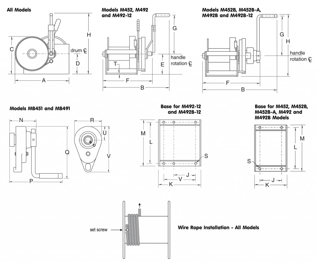
Hand Winches Dimensions — Models M452 and M492
| Spur Gear Double Reduction Hand Winches — Metric Dimensions | ||||||||||||||||||
| Model No. | Drum Dia. | Flange Dia. | Drum Width | A | B | C | D | E | F | G1 | H1 | J | K | L | M | S (hole dia.) | T | V |
| (mm) | (mm) | (mm) | (mm) | (mm) | (mm) | (mm) | (mm) | (mm) | (mm) | (mm) | (mm) | (mm) | (mm) | (mm) | (mm) | (mm) | (mm) | |
| M452 | 101.6 | 215.9 | 162.0 | 387.3 | 558.8 | 271.5 | 147.5 | 147.5 | 376.1 | 472.9 | 620.7 | 171.4 | 241.3 | 285.7 | 317.5 | 14.2 | 6.3 | — |
| M452B | 101.6 | 215.9 | 162.0 | 387.3 | 556.2 | 271.5 | 147.5 | 147.5 | 417.3 | 466.8 | 614.4 | 171.4 | 241.3 | 285.7 | 317.5 | 14.2 | 6.3 | — |
| M452B-A | 101.6 | 215.9 | 101.6 | 387.3 | 498.3 | 275.0 | 147.5 | 147.5 | 357.1 | 466.8 | 614.4 | 114.3 | 180.8 | 285.7 | 317.5 | 14.2 | 6.3 | — |
| M492 | 127 | 314.4 | 193.5 | 517.6 | 638.0 | 355.6 | 190.5 | 190.5 | 468.3 | 571.5 | 762 | 203.2 | 304.8 | 393.7 | 431.8 | 20.5 | 9.6 | — |
| M492B | 127 | 314.4 | 193.5 | 517.6 | 635 | 355.6 | 190.5 | 190.5 | 496.0 | 469.9 | 660.4 | 203.2 | 304.8 | 393.7 | 431.8 | 20.5 | 9.6 | — |
| M492-12 | 127 | 314.4 | 304.8 | 517.6 | 749.3 | 355.6 | 190.5 | 190.5 | 579.6 | 571.5 | 762 | 203.2 | 416.0 | 393.7 | 431.8 | 20.5 | 9.6 | 314.4 |
| M492B-12 | 127 | 314.4 | 304.8 | 517.6 | 746.2 | 355.6 | 190.5 | 190.5 | 607.0 | 469.9 | 660.4 | 203.2 | 416.0 | 393.7 | 431.8 | 20.5 | 9.6 | 314.4 |
Dimensions are for reference only and subject to change without notice.
1 Handles are adjustable. Dimension shown is for maximum handle length.
IMPORTANT: It is the owner’s or operator’s responsibility to determine the suitability of the equipment to its intended use. Study all applicable codes, manuals and regulations. Be sure to read the Owner’s Manual supplied with the equipment before operating it.
Disc Brake Dimensions — Models MB451 and MB491
| Disc Brake Dimensions — Models MB451/MB491 | ||||||
| Model No. | N | P | Q1 | R | U | V |
| (mm) | (mm) | (mm) | (mm) | (mm) | (mm) | |
| MB451 | 126.2 | 265.1 | 539.7 | 123.6 | 61.9 | 218.9 |
| MB491 | 130.8 | 269.7 | 543.0 | 123.6 | 61.9 | 268.2 |
Dimensions are for reference only and subject to change without notice.
1 Handles are adjustable. Dimension shown is for maximum handle length.
IMPORTANT: It is the owner’s or operator’s responsibility to determine the suitability of the equipment to its intended use. Study all applicable codes, manuals and regulations. Be sure to read the Owner’s Manual supplied with the equipment before operating it.